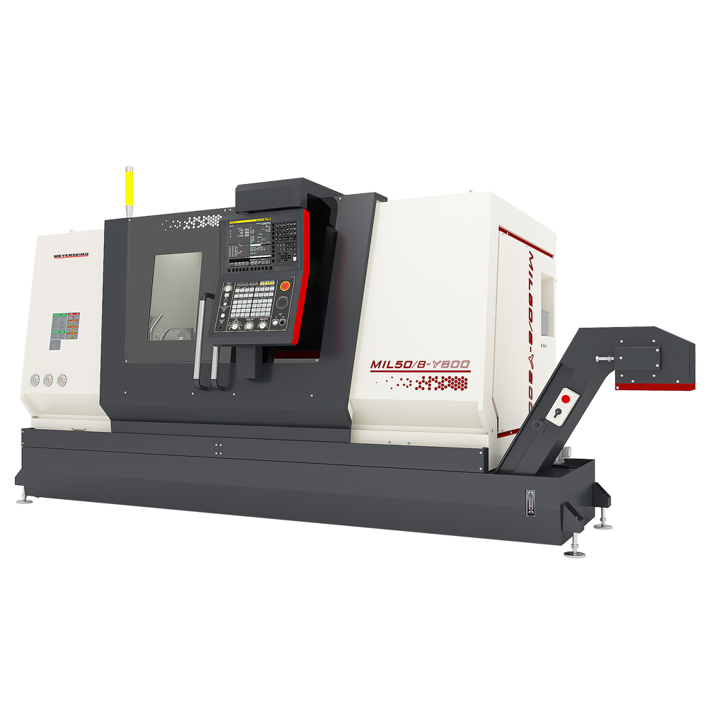
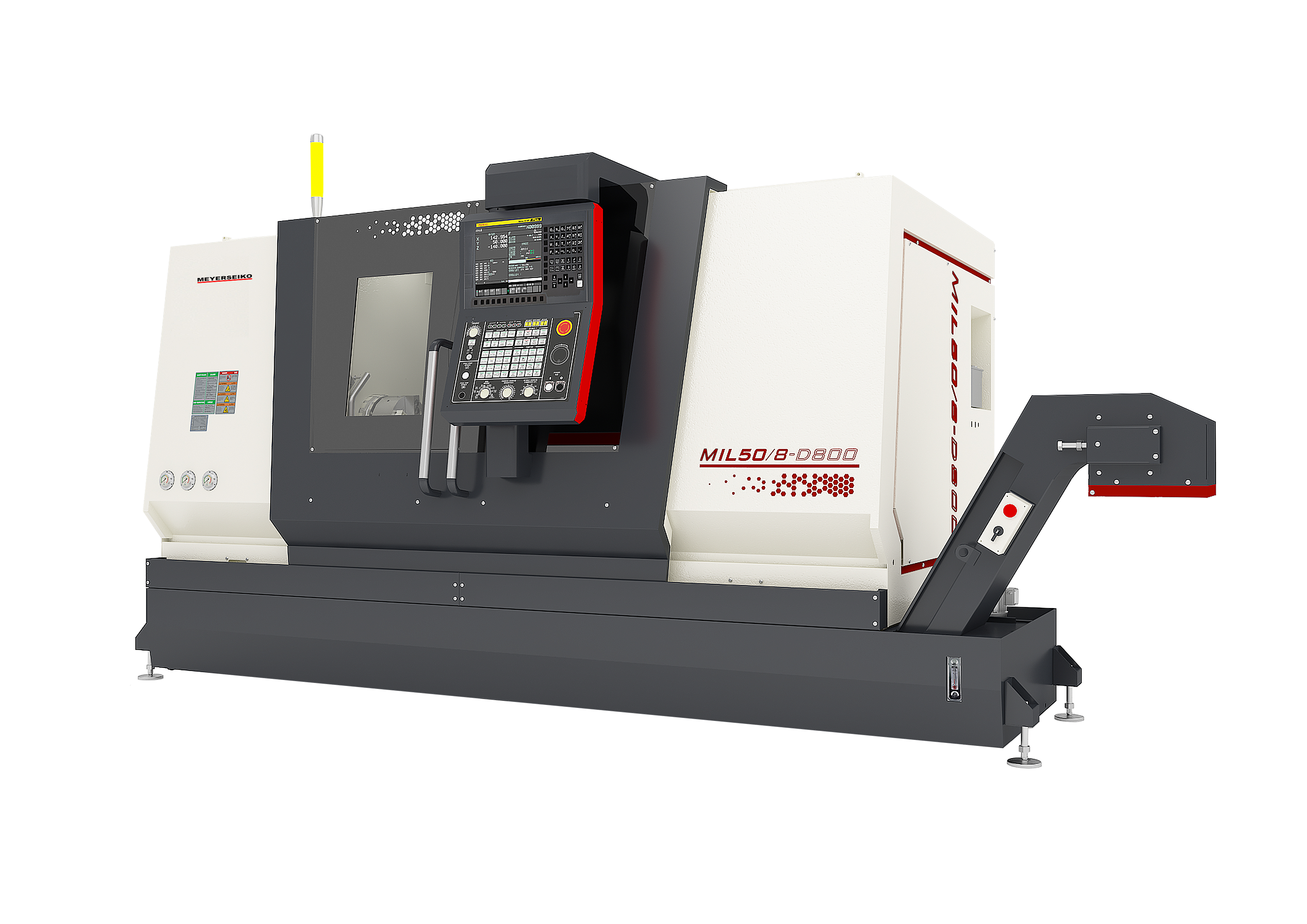
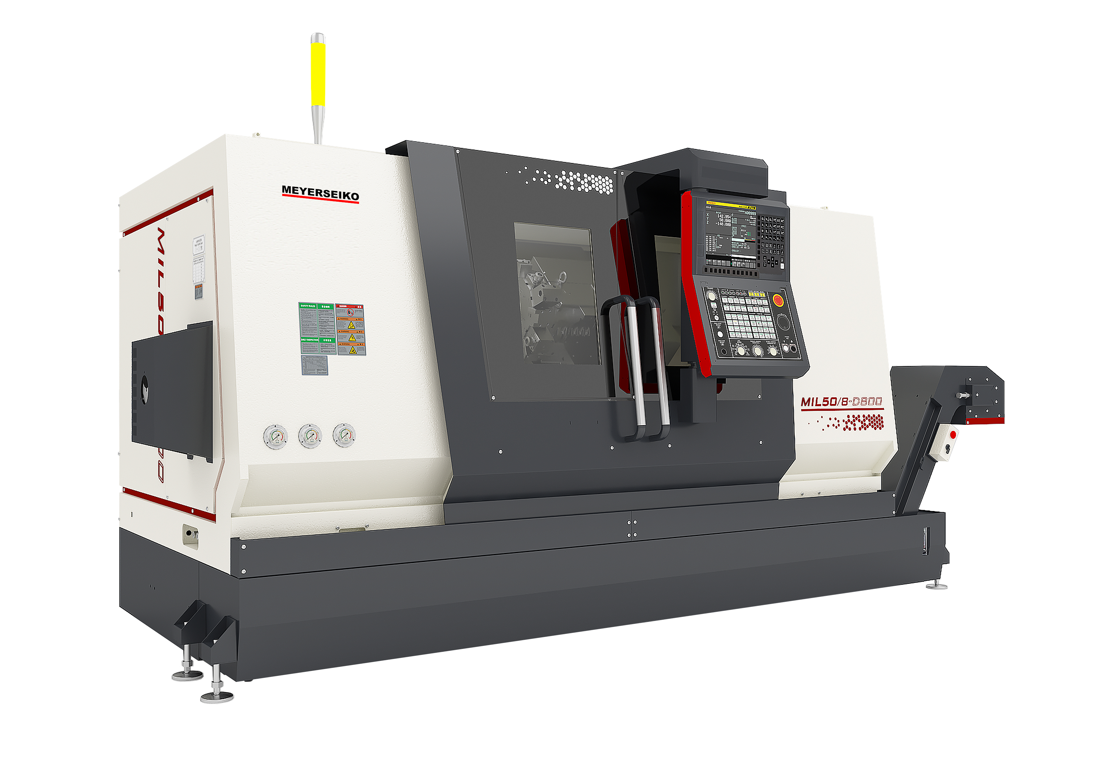
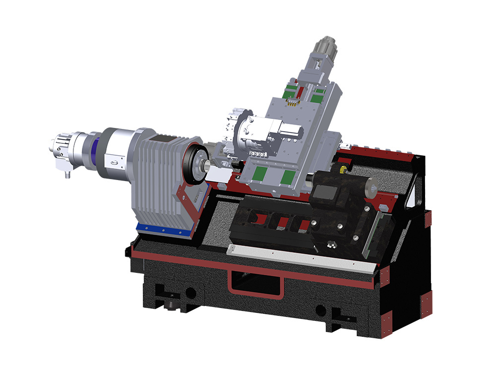
Slant Bed type Horizontal CNC Turning Center MIL50-800 Series with Turn Mill Function
Inclined Bed type Horizontal Turn Mill CNC Turning Center with driven tool turret
Turning and milling lathe center,Turn-Mill Center
Product Characteristics
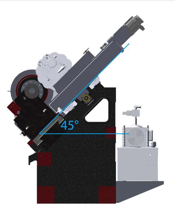
● 45° overall inclined bed design, high rigidity, smoother chip removal;
● Finite element structure analysis, reasonable layout of casting ribs, good force effect;
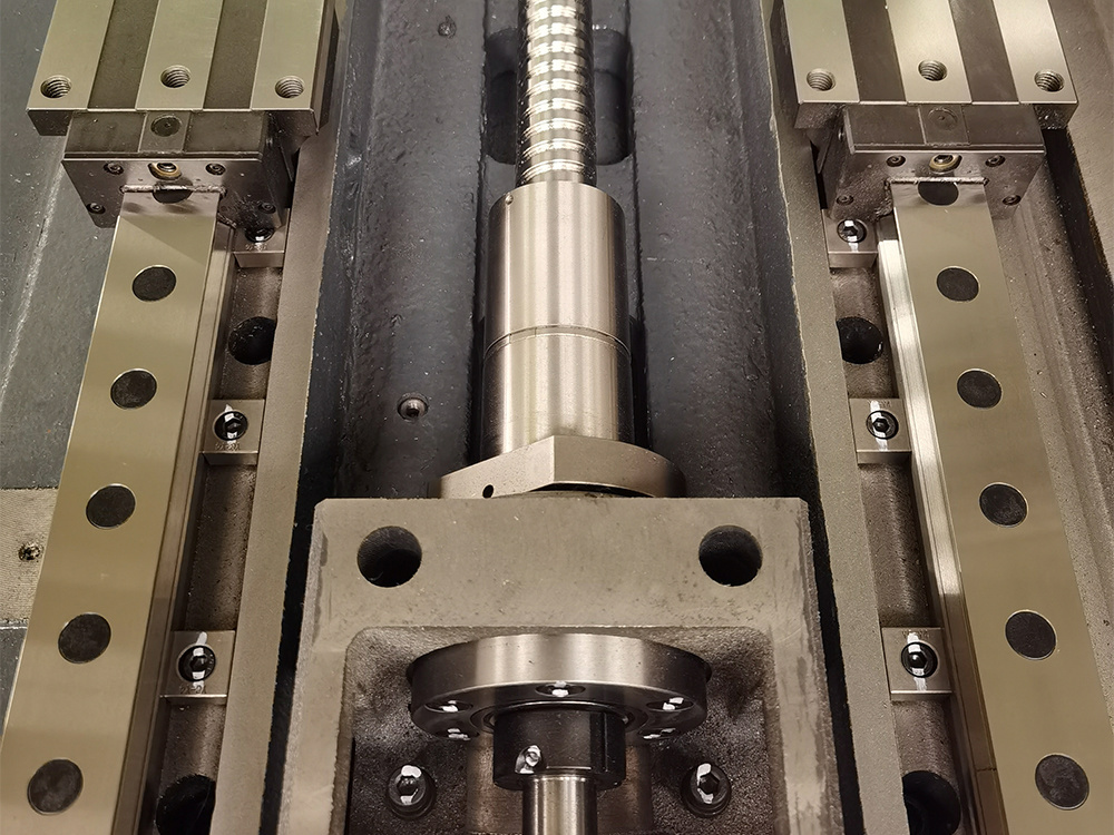
● X/Y/Z/A axis lead screws are all pre-stretched structures, which can reduce the influence of temperature rise on the accuracy of the lead screw during processing, and add oil seals to protect the screw bearing at the installation on both sides of the lead screw, and silent ball screws;
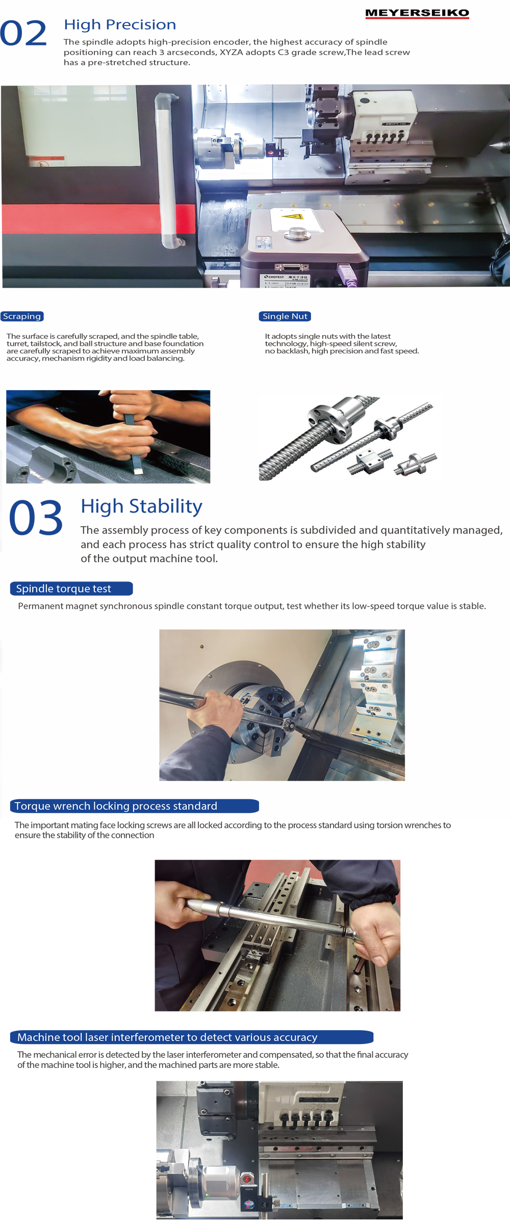
● The tailstock adopts V Type guide rail, strong heavy-duty rigidity, upper and lower layered structure, and a micro-adjustment device between the upper and lower layers, which is convenient for the tailstock top swing center to be fine-tuned in the X-axis direction, and the standard live center structure tailstock;
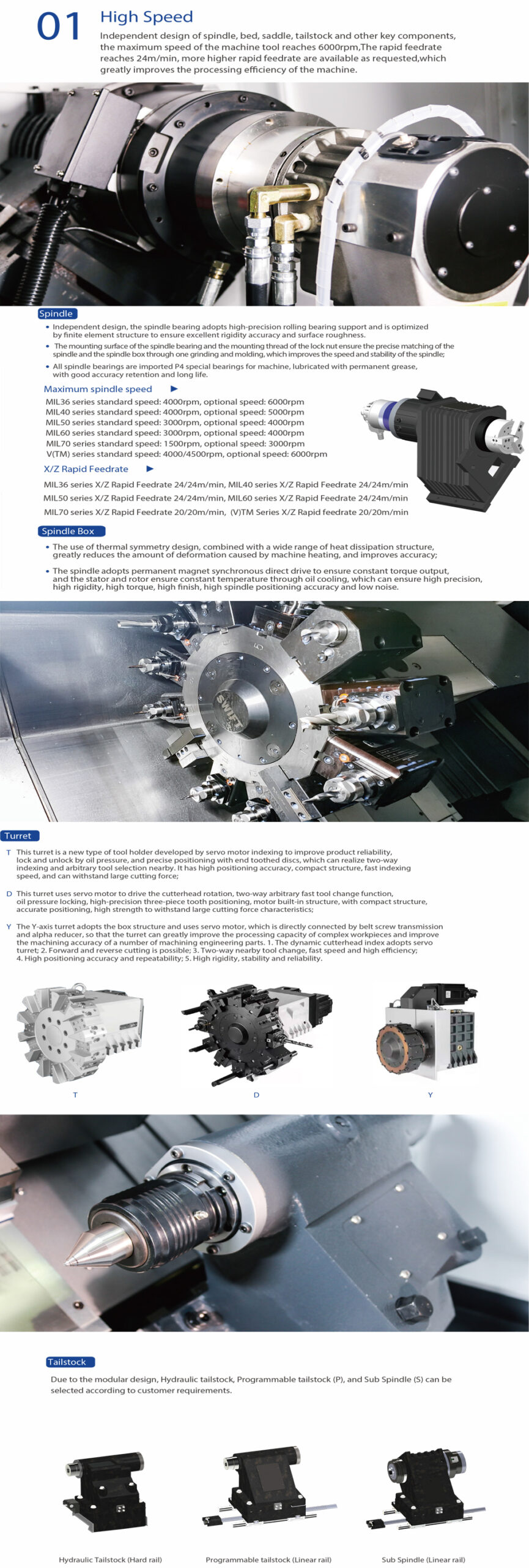
● MEYER SEIKO independently designed integrated permanent magnet synchronous headstock box, low noise, high precision, long life, high finish, constant torque output, high C-axis positioning accuracy;
● Wide range of options: such as feeders, parts catcher, large hollow chucks, enlarged spindle through-holes, tool setting instruments,Programmable tailstock, The second spindle can be docked at high speed,automated truss robot;
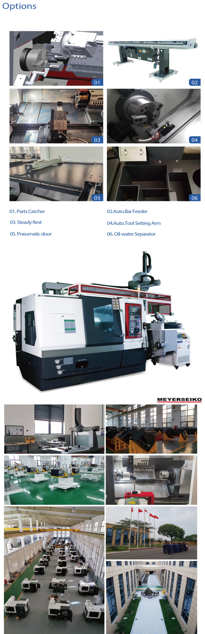
● The machine tool adopts modular design, and selects different functional equipment according to different customer product requirements, which can quickly realize the automation device and meet the needs of customers;
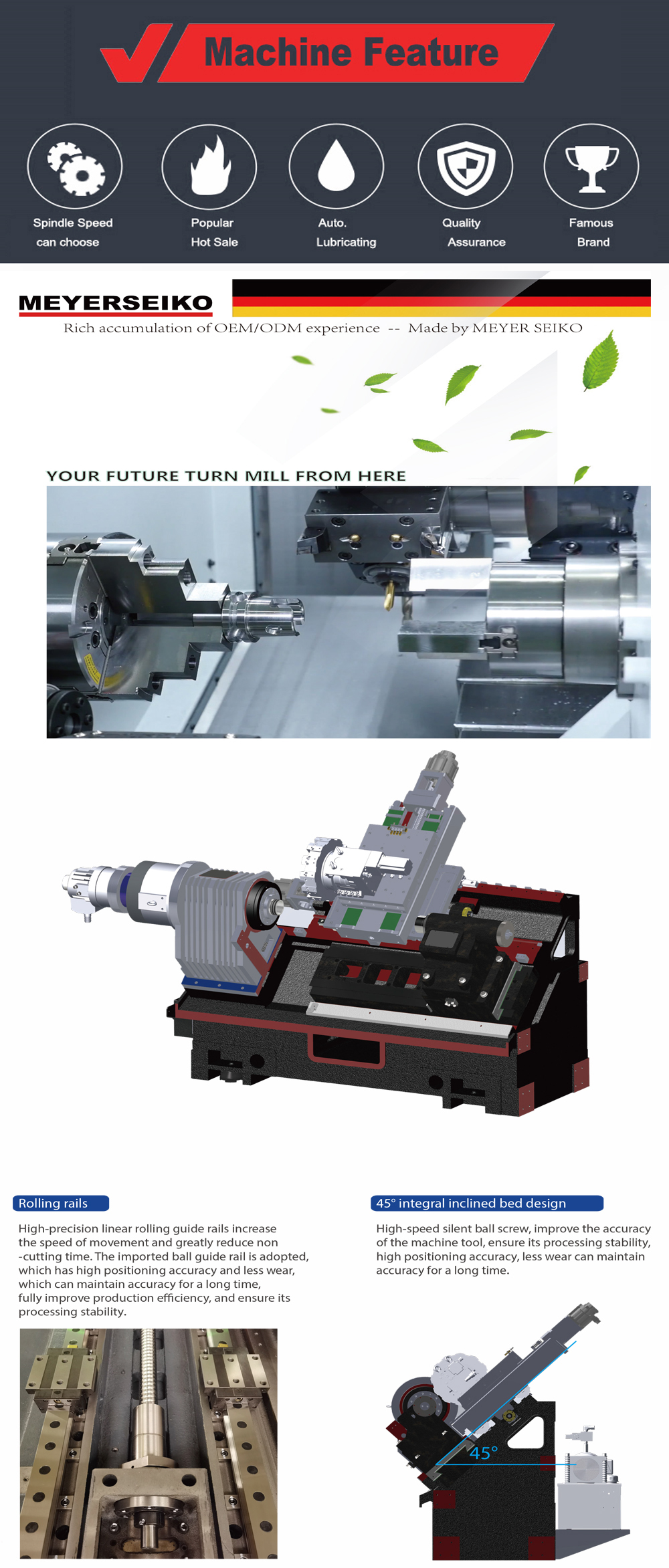
Rolling guide
High precision linear rolling guide, improve the moving speed, greatly reduce the non-cutting time. Imported ball guide rail, high positioning accuracy, less wear, can maintain accuracy for a long time, fully improve productivity, to ensure its processing stability.
45° overall tilt bed design
High-speed quiet ball screw, improve machine accuracy, ensure its processing stability, high positioning accuracy, less wear can maintain accuracy for a long time.
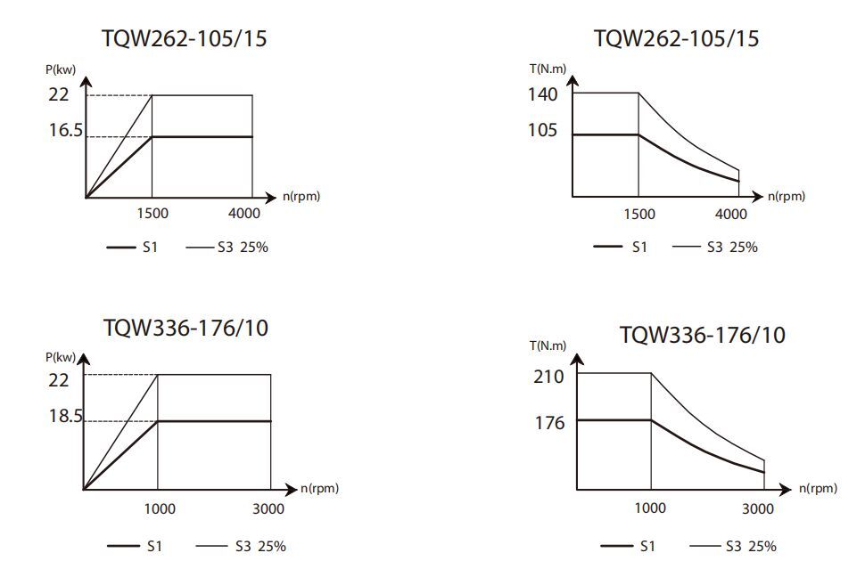
Spindle power torque
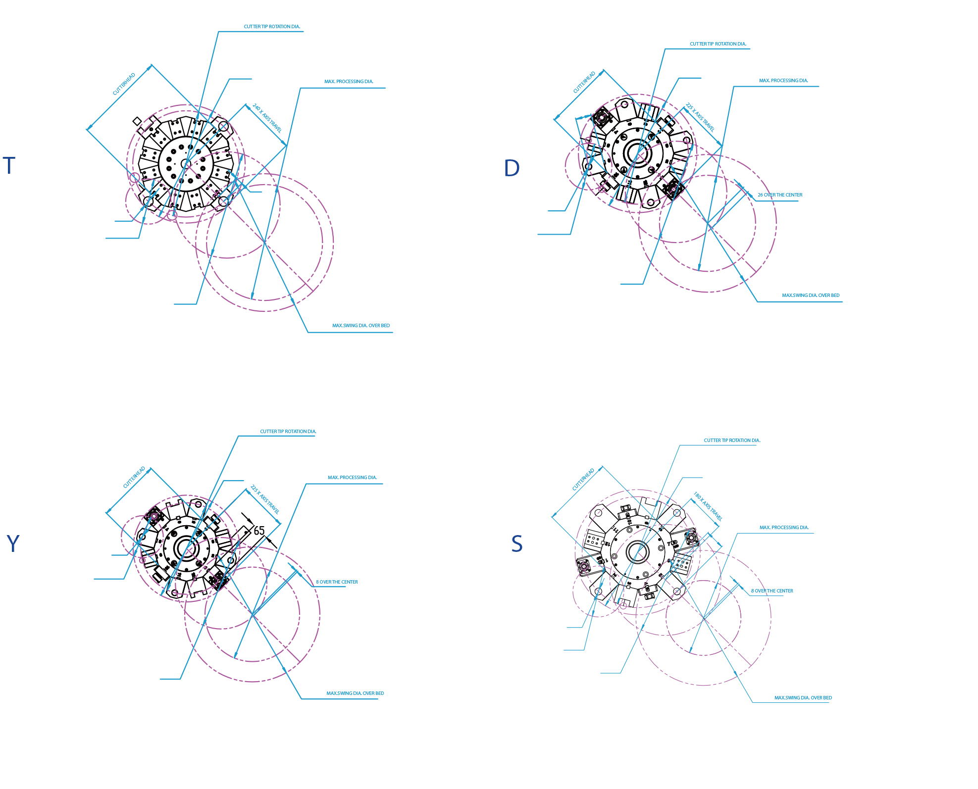
Tool interferogram
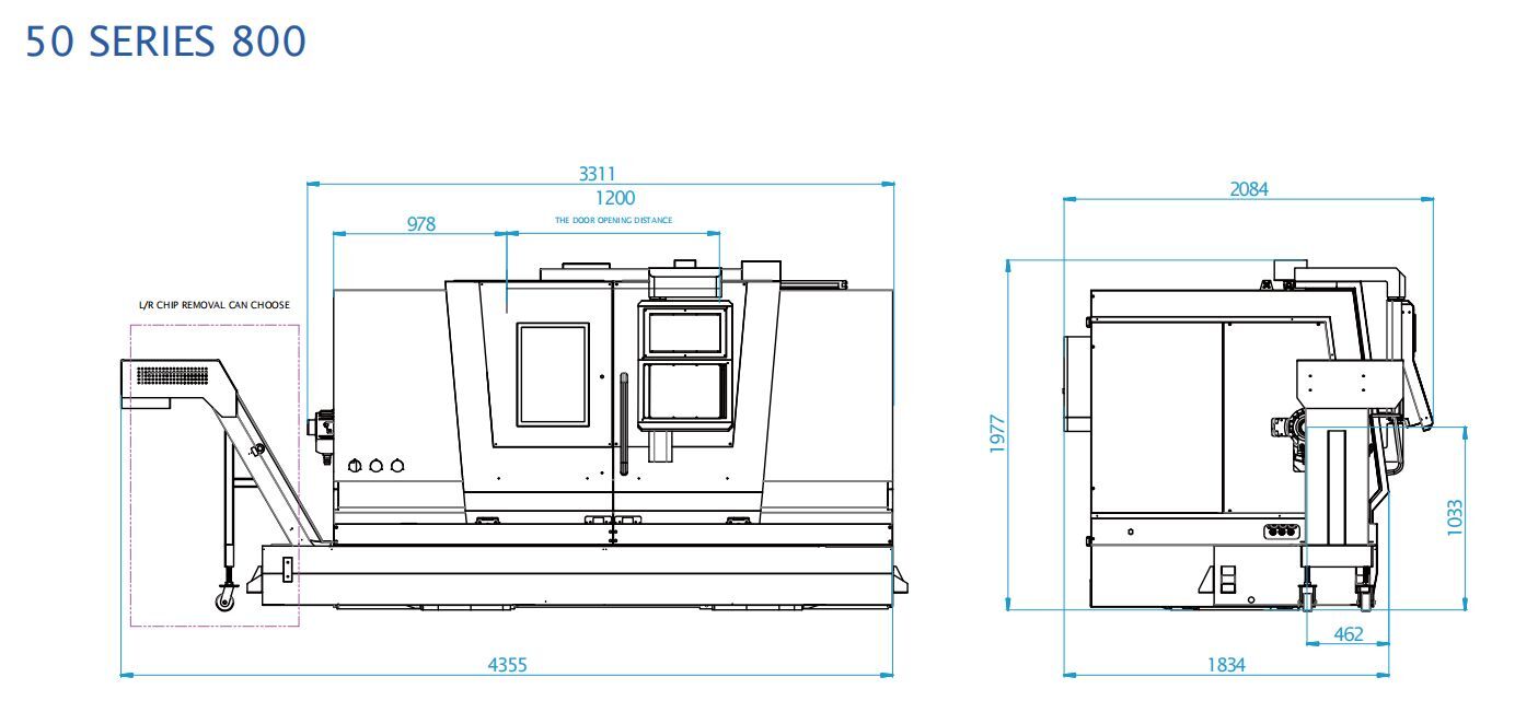
Dimensional Drawing
| Items | Unit | MIL50/6-T800 | MIL50/6S-T800 | MIL50/6-D800 | MIL50/6S-D800 | MIL50/6-Y800 | MIL50/6S-Y800 | MIL50/6-D800P | MIL50/6-T800P | MIL50/6-Y800P | ||
| Processing Range | Max.Swing dia.on Bed | mm | 570 | 570 | 570 | 620 | 620 | 620 | 570 | 570 | 620 | |
| Max.Cutting dia. | mm | 480 | 480 | 398 | 344 | 434 | 344 | 398 | 480 | 434 | ||
| Max.Cutting Length | mm | 800 | 800 | 766 | 764.5 | 764.5 | 764.5 | 766 | 800 | 764.5 | ||
| Max.bar dia.can pass | mm | 52 | 52 | 52 | 52 | 52 | 52 | 52 | 52 | 52 | ||
| Spindle | Max.Spindle Speed | rpm | 4000 | 4000 | 4000 | 4000 | 4000 | 4000 | 4000 | 4000 | 4000 | |
| Spindle Type | ISO | A₂-6 | A₂-6 | A₂-6 | A₂-6 | A₂-6 | A₂-6 | A₂-6 | A₂-6 | A₂-6 | ||
| Spindle Thru-hole dia. | mm | 61 | 61 | 61 | 61 | 61 | 61 | 61 | 61 | 61 | ||
| Spindle Taper | – | Metric 70 | Metric 70 | Metric 70 | Metric 70 | Metric 70 | Metric 70 | Metric 70 | Metric 70 | Metric 70 | ||
| Distance from Spindle center to floor | mm | 1032.5 | 1032.5 | 1032.5 | 1057.5 | 1057.5 | 1057.5 | 1032.5 | 1032.5 | 1067.8 | ||
| Sub-Spindle | Max.Spindle Speed | rpm | / | 2940 | / | 2940 | / | 2940 | / | / | / | |
| Spindle Type | ISO | / | A₂-5 | / | A₂-5 | / | A₂-5 | / | / | / | ||
| Spindle Thru-hole dia. | mm | / | 56 | / | 56 | / | 56 | / | / | / | ||
| Spindle Taper | – | / | MT6 | / | MT6 | / | MT6 | / | / | / | ||
| Hydraulic Tailstock | Tailstock Sleeve travel dia. | mm | 100 | / | 100 | / | 100 | / | / | / | / | |
| Tailstock Sleeve travel | mm | 125 | / | 125 | / | 125 | / | / | / | / | ||
| Tailstock Taper | Morse | 5# | / | 5# | / | 5# | / | / | / | / | ||
| Servo Tailstock | Tailstock Travel | mm | / | / | / | / | / | / | 850 | 850 | 850 | |
| Tailstock Taper | Morse | / | / | / | / | / | / | 5# | 5# | 5# | ||
| XYZA Axis Travel | X/Z Travel | mm | 240/825 | 240/825 | 225/825 | 180/825 | 225/825 | 180/825 | 225/825 | 240/825 | 225/825 | |
| Y/A Travel | mm | / | A850 | / | A850 | Y100 | 100/850 | A850 | A850 | 100/850 | ||
| X/Z Rapid Feedrate | m/min | 24/24 | 24/24 | 24/24 | 24/24 | 24/24 | 24/24 | 24/24 | 24/24 | 24/24 | ||
| Y/A Rapid Feedrate | m/min | / | A24 | / | A24 | Y 15 | 15/24 | A24 | A24 | 15/24 | ||
| Tool Turret | Tool Positions No. | – | 12 | 12 | 12 | 12 | 12 | 12 | 12 | 12 | 12 | |
| Turret Type | ||||||||||||
| Tool holder Size of Cylindrical turning tool | mm | 25×25 | 25×25 | 20×20 | 20×20 | 20×20 | 20×20 | 20×20 | 25×25 | 20×20 | ||
| Tool holder Max.dia. of Boring hole turning tool | mm | 40 | 40 | 32 | 32 | 32 | 32 | 32 | 40 | 32 | ||
| Accuracy | Positioning accuracy | X/Z | mm | ±0.006/300 | ±0.006/300 | ±0.006/300 | ±0.006/300 | ±0.006/300 | ±0.006/300 | ±0.006/300 | ±0.006/300 | ±0.006/300 |
| Y/A | mm | / | A±0.006/300 | / | A±0.006/300 | Y±0.006/300 | ±0.006/300 | A±0.006/300 | A±0.006/300 | ±0.006/300 | ||
| Re-Positioning accuracy | X/Z | mm | ±0.003 | ±0.003 | ±0.003 | ±0.003 | ±0.003 | ±0.003 | ±0.003 | ±0.003 | ±0.003 | |
| Y/A | mm | / | A±0.003 | / | A±0.003 | Y±0.003 | ±0.003 | A±0.003 | A±0.003 | ±0.003 | ||
| Total Power Capacity | kVA | 25 | 45 | 30 | 50 | 35 | 60 | 40 | 30 | 40 | ||
| Machine Size(L×W×H) | mm | 4355x2085x1980 | ||||||||||
| Machine Weight | kg | 5300 | 5500 | 5300 | 5500 | 5500 | 5700 | 5300 | 5300 | 5500 | ||
| CNC Controller | – | KND (SYNTEC/GSK/FANUC/SIEMENS Optional) | ||||||||||
| Servo Motor Torque Y | N.m | / | / | / | / | 9.6 | 9.6 | / | / | 9.6 | ||
| Hydraulic Chuck | inch | 8″ | ||||||||||
| [Hydraulic Center Support] | mm | Opt. | / | Opt. | / | Opt. | / | / | / | / | ||
| Chip Conveyor | – | Right/Left Side chip removal | ||||||||||
| Item | Unit | MIL50/8-T800 | MIL50/8S-T800 | MIL50/8-D800 | MIL50/8S-D800 | MIL50/8-Y800 | MIL50/8S-Y800 | MIL50/8-D800P | MIL50/8-T800P | MIL50/8-Y800P | ||
| Processing Range | Max.Swing dia.on Bed | mm | 570 | 570 | 570 | 620 | 620 | 620 | 570 | 570 | 620 | |
| Max.Cutting dia. | mm | 480 | 480 | 398 | 344 | 434 | 344 | 398 | 480 | 434 | ||
| Max.Cutting Length | mm | 785 | 785 | 751 | 749.5 | 749.5 | 749.5 | 751 | 785 | 749.5 | ||
| Max.bar dia.can pass | mm | 75 | 75 | 75 | 75 | 75 | 75 | 75 | 75 | 75 | ||
| Spindle | Max.Spindle Speed | rpm | 3000 | 3000 | 3000 | 3000 | 3000 | 3000 | 3000 | 3000 | 3000 | |
| Spindle Type | ISO | A₂-8 | A₂-8 | A₂-8 | A₂-8 | A₂-8 | A₂-8 | A₂-8 | A₂-8 | A₂-8 | ||
| Spindle Thru-hole dia. | mm | 86 | 86 | 86 | 86 | 86 | 86 | 86 | 86 | 86 | ||
| Spindle Taper | – | Metric 90 | Metric 90 | Metric 90 | Metric 90 | Metric 90 | Metric 90 | Metric 90 | Metric 90 | Metric 90 | ||
| Distance from Spindle center to floor | mm | 1032.5 | 1032.5 | 1032.5 | 1057.5 | 1057.5 | 1057.5 | 1032.5 | 1032.5 | 1057.5 | ||
| Sub-Spindle | Max.Spindle Speed | rpm | / | 2940 | / | 2940 | / | 2940 | / | / | / | |
| Spindle Type | ISo | / | A₂-5 | / | A₂-5 | / | A₂-5 | / | / | / | ||
| Spindle Thru-hole dia. | mm | / | 56 | / | 56 | / | 56 | / | / | / | ||
| Spindle Taper | – | / | MT6 | / | MT6 | / | MT6 | / | / | / | ||
| Hydraulic Tailstock | Tailstock Sleeve travel dia. | mm | 100 | / | 100 | / | 100 | / | / | / | / | |
| Tailstock Sleeve travel | mm | 125 | / | 125 | / | 125 | / | / | / | / | ||
| Tailstock Taper | Morse | 5# | / | 5# | / | 5# | / | / | / | / | ||
| Servo Tailstock | Tailstock Travel | mm | / | / | / | / | / | / | 850 | 850 | 850 | |
| Tailstock Taper | Morse | / | / | / | / | / | / | 5# | 5# | 5# | ||
| Travel | X/Z Travel | mm | 240/825 | 240/825 | 225/825 | 180/825 | 225/825 | 180/825 | 225/825 | 240/825 | 225/825 | |
| Y/A Travel | mm | / | A850 | / | A850 | Y100 | 100/850 | A850 | A850 | 100/850 | ||
| X/Z Rapid Feedrate | m/min | 24/24 | 24/24 | 24/24 | 24/24 | 24/24 | 24/24 | 24/24 | 24/24 | 24/24 | ||
| Y/A Rapid Feedrate | m/min | / | A24 | / | A24 | Y 15 | 15/24 | A24 | A24 | 15/24 | ||
| Tool Turret | Tool Positions No. | – | 12 | 12 | 12 | 12 | 12 | 12 | 12 | 12 | 12 | |
| Turret Type | ||||||||||||
| Tool holder Size of Cylindrical turning tool | mm | 25×25 | 25×25 | 20×20 | 20×20 | 20×20 | 20×20 | 20×20 | 25×25 | 20×20 | ||
| Tool holder Max.dia. of Boring hole turning tool | mm | 40 | 40 | 32 | 32 | 32 | 32 | 32 | 40 | 32 | ||
| Accuracy | Positioning accuracy | X/Z | mm | ±0.006/300 | ±0.006/300 | ±0.006/300 | ±0.006/300 | ±0.006/300 | ±0.006/300 | ±0.006/300 | ±0.006/300 | ±0.006/300 |
| Y/A | mm | / | A±0.006/300 | / | A±0.006/300 | Y±0.006/300 | ±0.006/300 | A±0.006/300 | A±0.006/300 | ±0.006/300 | ||
| Re-Positioning accuracy | X/Z | mm | ±0.003 | ±0.003 | ±0.003 | ±0.003 | ±0.003 | ±0.003 | ±0.003 | ±0.003 | ±0.003 | |
| Y/A | mm | / | A±0.003 | / | A±0.003 | Y±0.003 | A±0.003 | A±0.003 | ±0.003 | |||
| Total Power Capacity | kVA | 30 | 50 | 35 | 55 | 40 | 65 | 45 | 35 | 45 | ||
| Machine Size(L×W×H) | mm | 4355x2085x1980 | ||||||||||
| Machine Weight | kg | 5400 | 5600 | 5400 | 5600 | 5600 | 5800 | 5400 | 5400 | 5600 | ||
| CNC Controller | – | KND (SYNTEC/GSK/FANUC/SIEMENS Optional) | ||||||||||
| Spindle Motor Torque | N.m | 210 | 210 | 210 | 210 | 210 | 210 | 210 | 210 | 210 | ||
| Hydraulic Chuck | inch | 10″ | ||||||||||
| [Hydraulic Center Support] | mm | Opt. | / | Opt. | / | Opt. | / | / | / | / | ||
| Chip Conveyor | – | Right/Left Side chip removal | ||||||||||
CNC lathe is one of the widely used CNC machine tools. It is mainly used for cutting the inner and outer cylindrical surfaces of shaft or disc parts, inner and outer conical surfaces with arbitrary cone angles, complex rotating inner and outer surfaces, cylindrical and conical threads, and can perform groove cutting, drilling, expanding, reaming, and boring.